Convert 5V to 3.3V

Well, my first mistake in the project. I don’t know why I didn’t read this correctly, but my Pitot module does not deliver PWM but Analog signal between 0 and 5V. The NAVIO+ board has four analog inputs, two of them are used by the power module (one for battery voltage, one for current), so I have two left. The problem is, it must be max 3.3V and the Pitot delivers 5V.

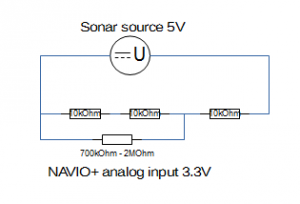
Goal is to convert 5V to 3.3V at insignificant current. The easiest is to use resistors to divide the voltage, since 3.3V is 2/3 of 5V, three resistors of identical value in serial will divide the voltage by 3. Plug over two, you’ve got 2/3. The only problem is which resistor value to choose. The internal resistance of the analog input of the NAVIO+ board is between 700kOhm and multiple MOhm. So the resistors use must be significantly lower than that to avoid any influence of the input impedance. But if your resistors are too lower, the Pitot module will not be able to deliver the current. The Pitot module can deliver at least 1mA.

Remember U = R * I ? (U=Volt, R=Ohm, I=Ampere).

5V = ? * 0.001A => 5 / 0.001 = 5kOhm (all three together)

On the other side, to avoid any influence from the variable impedance of the analog input, the resistors should be at least 50 times lower. 700kOhm / 50 = 35kOhm (value of two resistors).

5000 / 3 < my_resistor < 35000 / 2

So I’ve chosen arbitrarily the value of 10kOhm.

If you haven’t followed the logic, maybe this little drawing helps.

Untitled 1

Finally we have the following:

Max Input: 5V
Max Output: 3.3V
Max Current: 0.17mA
Max Dissipated energy: 0.85mW

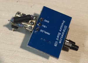
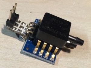
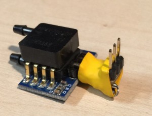
Here a few pictures of the adapter. I’m not especially proud of the board and soldering but I haven’t done real electronics (with appropriate tools) for a while.

apater_5v_3.3v_1 apater_5v_3.3v_2apater_5v_3.3v_3


Which plane?

For my testing I need a plane, possibly foam / styro. It should have a large fuselage for all the electronics, probably something with a wingspan over 1500mm if not over 2000mm. Maybe a glider (slow flying might help with the first tests). Unfortunately most of them have a tight fuselage.

If anyone has an idea, please comment.

Project start, the hardware

I just decided to start this blog to talk about my recent project start. As a network engineer I do play a lot with networking hardware, but also embedded systems and have acquired quite some knowledge about them. Last week, the idea of an RC autopilot emerge in my mind. Not that I never thought about it, but this was different, it was one of those ideas you feel comfortable about being able to actually do it. So I started my research of products that would fit my needs. I have a rough idea about the kind of sensors I needed:

  • PWM output (servo control)
  • 3D positioning (like all the smartphones, gyroscope and accelerometer)
  • Maybe some GSM or WLAN
  • Barometer for altitude
  • GPS

On a second thought, I decided to add PWM input to the list. This would help to regain control with controller or do a takeoff or landing manually.

  • PWM input (to read the sero settings from the RC receiver)

Another thing my project needs is a computer. I mean, a real computer, not some programmable controller. I want something I can write my own code either C or perl. As I quickly discovered during my research is that such modules exist already, but they’re “ready to use” hardware. Not interesting and not interested!

  • Real computer running linux, possibly debian, possibly x86 or arm or mips.

After a few evenings and nights surfing the incredibly full of information web, I came up with this list of hardware:

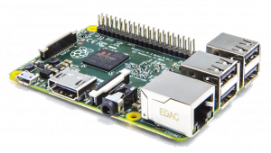
RaspberryPI 2

It is a real computer! runs on 5V USB power, has enough RAM and all the I/O needed. And it will have debian 😉

Pi2ModB1GB_-comp

NAVIO+

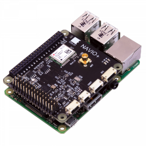
I discovered NAVIO+ by luck. It is a great module that integrates almost everything I need and it is a piggy bag for the RaspberryPI ! It looks nice and fits just perfectly on the Raspberry PI 2.

  • 1 PPM input (servo, all in one signal)
  • 12 PWM output (servo)
  • Barometer (altimeter)
  • 3D sensors (gyroscope, accelerometer)
  • GPS and GLONASS

Navio-B-3D-1-small

(On the picture, it is already plugged on a Raspberry PI)

3DR 8 Channel PPM Encoder (v3)

ppm-encoder-wiring

I quickly noticed the NAVIO+ module only has PPM input. As I’m a Spektrum user, my receiver does not have the PPM signal, only the PWM for each servo is available. So I needed a bit of hardware that would convert multiple PWM into PPM. This little chip does all that at once. Simple and efficient.

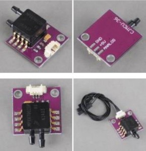
APM 2.5/2.6 Airspeed Sensor Board MPXV7002DP

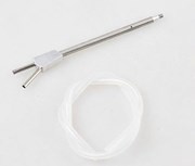
Oh yeah, that’s the thing. A real pitot tube sensor. GPS is fine, but not accurate enough to measure speed for a plane, especially not for an RC plane that rapidly changes speed. This sensor generate PWM signal, I piece of cake to integrate 😉

445192-ASP_b1445193-AYT_b1

MB1030 LV-MaxSonar®-EZ3™

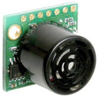
A little sonar, yes I know, it wasn’t on the original list. But I thought, if I want to do autolanding, the barometer will probably not be accurate enough for the last seconds before crash. This sonar can measure up to ~6 meters distance. Perfect for the final steps of a smooth landing (the barometer and the GPS will do the measurements until the sonar is in range).

LV-EZ Ultrasonic Range Finder_200px

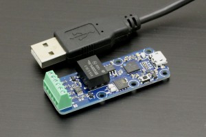
Yocto-PWM-Rx

As I didn’t want to spend the PPM encoder inputs, I also ordered this Yocto-PWM-Rx PWM decoder module. It was two inputs and is USB powered. USB also provides the data link. I will use this to connect the sonar and the speed sensor. Reading it 10 or 20 times a second should be enough.

illustr-yocto-pwm-rx-2-big


RCAP